Cylindrical workpieces tempt buyers into a simple purchase decision: calculate weight, select a turning-roll capacity, and start welding. That approach misses the real question. Vessels, pipe spools, shells, and drums behave differently once they are loaded, aligned, fitted, rotated, welded, inspected, and released. Diameter and nominal weight matter, but neither explains how reliably the work will move through the station.
Select the rotation system as a flow-control system. Its job is not only to turn a part. It must keep contact stable, preserve alignment, present the joint at the required travel condition, and allow the next operation to start without an improvised recovery. When a shop evaluates those functions together, it can tell the difference between a roller set that merely moves steel and one that supports a repeatable welding route.
Diameter, tonnage, and a catalogue photograph can give false comfort
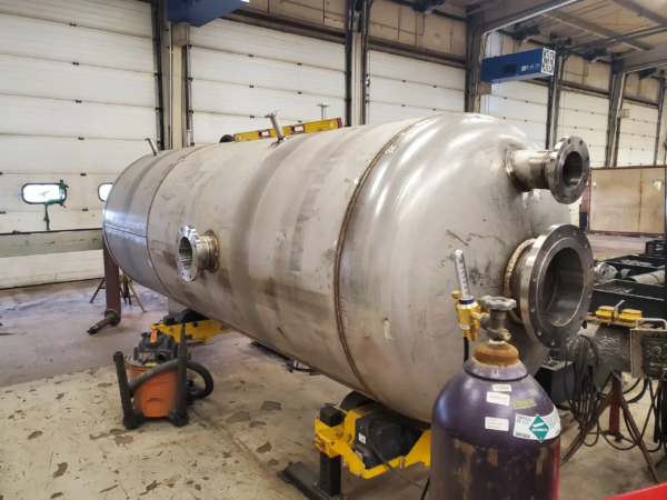
Two shells with the same diameter can demand very different handling. One may have uniform wall thickness and clean circular ends. Its counterpart may carry nozzles, stiffeners, an offset seam, temporary attachments, or an out-of-round condition from previous forming. One can be loaded by a crane over the rollers; the other must be fed through a constrained bay. One needs a single girth weld; the other needs repeated internal and external operations.
Those differences affect the contact pattern between workpiece and rollers, the risk of axial drift, the time needed to set up a fit-up station, and whether the welding head can reach the seam. Treat a nominal rated load as an entry condition, not proof that the system suits the job. Review the workpiece drawing, support points, likely eccentricity, and intended orientation together.
Work design also has a human consequence. Reaching over a rotating shell, fighting a misaligned joint, or repeatedly moving a control station can add force, awkward posture, and repetition to a job. OSHA’s ergonomics guidance is a helpful reminder that material handling and workstation design belong in the same conversation as speed and capacity.
Cylinder Flow Stability Check
Before asking for a model number, run the Cylinder Flow Stability Check on a representative part family. It is a short decision protocol designed to surface the assumptions that cause expensive changes later.
Begin by defining the real envelope. Record diameter range, length, wall thickness, normal and maximum mass, attachments, and credible center-of-gravity offset.
Next, map each contact. Identify how the shell arrives, how it is set on the rolls, where it is restrained, and how it is removed after welding.
Then state the motion requirement. Is the need continuous circumferential welding, indexed rotation, fit-up movement, or a mix of modes?
After that, trace the weld head. Confirm reach, clearance, cable management, and whether the head must travel independently of rotation.
Finally, plan the abnormal case. Define what the operator does if the workpiece drifts, slips, arrives out of round, or must be stopped mid-cycle.
Suppliers can respond far more usefully to this evidence than to a request for “a 20-ton rotator.” The check creates an auditable basis for discussing drive and idler configuration, self-aligning versus conventional support, control arrangement, anti-drift measures, loading method, and fixtures.
Choose support architecture by contact behavior
The first architectural choice is not brand; it is how the workpiece should be supported. Conventional turning-roll arrangements may make sense where diameter is controlled and the team wants predictable, deliberately set roller spacing. Self-aligning routes may be attractive where the working diameter changes within a defined range and faster accommodation matters. In either case, a buyer must validate the actual contact condition for the part, not assume that a generalized product image represents every shell.
For very short components, abrupt geometry changes, or a part that must be tilted rather than simply rotated, a positioner or a dedicated fixture can be more appropriate than rolls. Long vessels that need vertical and horizontal weld-head reach may require rolls to work with a column-and-boom manipulator rather than carry the whole productivity burden alone. Material flow determines the combination.
On its published product overview, Wuxi ABK Machinery distinguishes welding rotators and turning rolls from positioners, column-and-boom manipulators, robotic systems, and production lines. It lists rotator capacities as a broad equipment family rather than a one-size-fits-all commitment, which is the right way to begin a matching conversation: identify the support architecture first, then validate a detailed specification against the workpiece.
Aubrik’s current turning-roll page publishes a 1-1,000 T load family, 200-6,000 mm diameter range, and 0.5-15 rpm inverter speed. Treat those numbers as a category screen, not as approval for a shell with appendages, eccentric loading, or an unstable contact condition; Aubrik still needs the shell drawing, wall thickness, and handling route to size the working arrangement.
Size the transfer route before choosing the rollers
One frequent failure mode is to specify the rollers and only then discover that the crane approach, rail length, fit-up station, or inspection route does not support the promised cycle. Diagram the transfer route at the same time as the rotation system. Include the load path, the location of lifting points, available headroom, staging area, blocking requirements, and how a finished vessel clears the station.
Route elementQuestion to answerEvidence to obtain before release
Incoming loadCan the workpiece reach the roller centerline without a side pull?Crane sketch and rigging plan
Fit-upCan joint alignment occur without blocking the next load?Fixture layout and clearance dimensions
WeldingCan the controls and welding head remain accessible across the full length?Reach envelope and cable-routing concept
InspectionWhere does the part stop for visual, dimensional, or other checks?Hold-point sequence and safe access plan
ReleaseCan the finished component leave without reversing the entire route?Exit path and buffer capacity
This is why “capacity” can be misleading. Even a station that carries the calculated mass can produce poor daily output when material handling is sequenced badly. Process mapping reveals whether a second set of rolls, a transfer cart, longer rails, a fixture zone, or a changed bay layout is more valuable than a higher nominal rating.
Pair weld-head reach with rotation control
Rotation should be specified relative to the weld process. Continuous movement may suit a simple circumferential seam; a multi-operation vessel may need repeatable indexing, controlled starts and stops, or a plan for the operator to work at several axial positions. Where the head needs controlled reach while the workpiece rotates, a manipulator-and-rolls combination often makes sense. That differs from treating a manipulator as a luxury add-on.
Aubrik’s published system map places welding manipulators in a different operating scale from turning rolls and describes column-and-boom reach as a cell-level consideration. That separation is useful for planning: it asks whether the current constraint is support, reach, or both. Test the farthest weld location and the least favorable position in a trial layout, not only the easy center section.
Use handoff tests to expose false capacity and limits
Before accepting a proposed configuration, write a short factory acceptance scenario around an actual part or a credible surrogate. Include loading, locating, initial rotation, a stop-and-restart condition, access to the far-end seam, a planned inspection stop, and removal. Observe where an operator must reach, where a cable is vulnerable, where a crane needs to wait, and whether the workpiece stays controllable through the full sequence.
During the trial, time the non-welding actions as carefully as the rotation itself. Photographs of support contact, operator stance, and the transfer path make later layout decisions less dependent on memory.
Document the test with the same seriousness as a capacity calculation. Record workpiece dimensions, assumed mass, support positions, motion settings, control method, and any fixture used. If a supplier proposes a substitute part, identify the missing differences rather than treating the test as automatically equivalent. Only a clean demonstration that preserves those conditions is useful.
Limits and trade-offs that deserve a direct answer.
Turning rolls are not a universal response to cylindrical fabrication. They may be a poor fit where the component is too short to establish stable support, where appendages produce unpredictable contact, where a large offset load needs a different restraint strategy, or where frequent product changes make dedicated setup burdensome. Self-aligning equipment can simplify some diameter variation, but it does not remove the need to evaluate the shell, loading method, controls, and safety system.
There is also a trade-off between flexibility and repeatability. Highly adaptable stations can support more workpiece types, but they may require more adjustment and operator judgment. Dedicated routes can be faster and easier to verify, but they may be uneconomical for a volatile product mix. Actual demand, expected mix, available lifting capacity, and the cost of fixture changes should shape the decision — not an aspiration to automate every cylinder.
Put operating constraints into the purchase order.
A sound specification describes more than load and speed. It should include the workpiece envelope, contact assumptions, required control modes, proposed safety functions, fixture scope, loading route, weld-head interface, utility requirements, training, commissioning tests, records, and acceptance criteria. ISO 12100’s risk-assessment approach supports this kind of explicit definition because it treats safe machinery use as a design problem with residual risks to be identified and managed.
That discipline creates a better outcome for both buyer and supplier. Ultimately, the final system may still be a simple set of rolls, or it may grow into a coordinated station with a manipulator and dedicated flow controls. Either way, the objective is stable movement through the work — not just visible rotation on the shop floor.